PROJECTS
Brian Teo's Selected Projects. Brian’s projects showcase his skills in hardware, software, and system integration, highlighting his ability to design and develop practical engineering solutions.
Download ResumeAutomatic Door Sensor
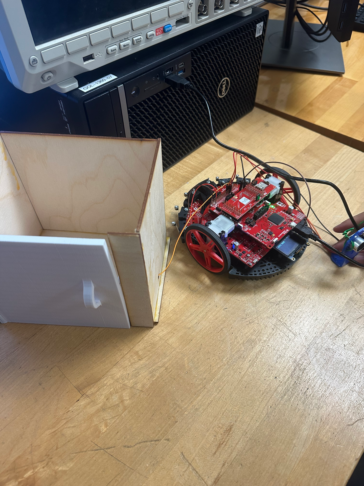
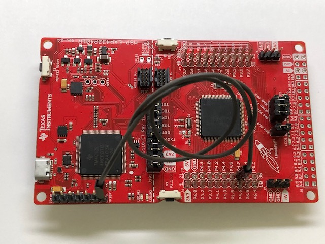
For this project, I designed and implemented a secure, interactive automatic door locking system using a TI MSP432 microcontroller, a CC2650 Bluetooth module, an ultrasonic sensor, a servo motor, and an OLED display. The system responds to Bluetooth commands and real-time sensor data, offering both manual and automatic operation modes.
The door can be controlled via a smartphone app over Bluetooth, supporting three commands:
- Lock Mode (Command 1): Rotates the servo to engage the lock.
- Unlock Mode (Command 2): Rotates the servo to release the lock.
- Auto Mode (Command 3): Activates an ultrasonic sensor that measures proximity and automatically locks or unlocks the door based on detected distance.
At the core of the system is the MSP432 microcontroller, which coordinates all logic and peripheral communication. The CC2650 Bluetooth BoosterPack receives wireless commands from a smartphone, enabling remote door control. An ultrasonic sensor (trigger/echo pins) calculates distance using time-of-flight measurements, while a servo motor physically performs the lock/unlock action based on the current mode.
I programmed the servo using PWM control, which was initialized in ServoInit() and was used in the Servo() function. The calibrated pulse widths were 2200 µs for locking and 5250 µs for unlocking. Commands are received through the variable BT_ByteData and processed by the MoveRobot() function, which interprets user input to execute the appropriate servo action.
An SSD1306 OLED display provides real-time feedback, showing both the current lock state and measured distance. The display module used in the TI-RSLK kit is the SSD1306 128×64 dot-matrix OLED (Organic Light-Emitting Diode) graphical display. It is a compact and energy-efficient screen used often in embedded systems for displaying text and graphics. The SSD1306 operates using a Serial Peripheral Interface (SPI) communication protocol, which allows the MSP432 microcontroller to transmit data efficiently through a small number of pins. On the MSP432 LaunchPad, the display is wired through Port 9, where each pin serves a specific role in SPI communication. Pin P9.7 functions as the SPI UCA3SIMO (LCDMOSI) line and is responsible for sending data from the microcontroller to the display. Pin P9.5 acts as the SPI UCA3CLK (LCDSCLK) and provides the clock signal that syncs data transmission. Pin P9.4 is the SPI UCA3STE (LCDCS), which serves as the chip select line that enables communication with the OLED when active. Two additional GPIO pins are used for control: P9.6 (LCDDC), which determines whether the transmitted byte is a data or command instruction and P9.3 (LCDRST), which provides a hardware reset signal to initialize or restart the display. Both these connections allow the MSP432 to send graphical data, control commands, and initialization sequences directly to the SSD1306 driver, enabling real-time updates of text, icons, and sensor readings on the OLED screen.
I implemented timing through TimerA modules to sync PWM signals and ultrasonic pulse measurement. The distanceInCm() and pulseIn() functions calculate distance by measuring the echo pulse duration and converting it to centimeters.
In Auto Mode, the door unlocks automatically when an object (such as a person’s hand or body) is detected within 10 cm, and re-locks once the object moves away.
One of the biggest challenges was the mechanical design of the locking mechanism. I originally planned to entirely print the project, but because of size inaccuracy and a long wait time, the prints were unreliable. In order to solve this, I decided to redesign the components in CAD and laser-cut them from wood. This had similar precision while keeping fabrication quick and accessible.
Another major issue involved power instability. The OLED screen would frequently crash when the system drew too much current. After testing several configurations, I identified the root cause as a weak base-board battery and resolved it by replacing the power source. This stabilized the entire system and ensured reliable display performance during operation.
This project demonstrated how embedded systems, sensors, and wireless communication can be combined to create a smart and secure door-locking solution. I learned how to integrate multiple peripherals on the MSP432 platform, manage real-time tasks with timers, and debug both software and hardware issues while given limited time.
If I were to continue improving this project, I would integrate authentication features like a keypad, password entry, or fingerprint reader for enhanced security. This could be done by adding a new authentication routine that checks user input before sending lock or unlock signals to the servo. For example, I would make the system compare a typed password or fingerprint ID with stored values in memory before allowing any access. I would also change the mechanical design for faster 3D-printing and an overall more pleasing design. I would also like to include a small DC motor to automatically open the door once it’s unlocked, which would involve adding a simple motor control function triggered right after the unlock command. More functions such as LED or sound indicators can be programmed through GPIO pins to give visual or audio feedback when switching modes or confirming access. Lastly, a security alarm feature could be implemented by using the ultrasonic sensor to continuously monitor for unexpected movement while the door is in the locked state. This involves adding a loop that checks for sudden distance changes, such as an object moving closer than a set threshold number when the door is supposed to be locked. If this condition is detected, the system could trigger an interrupt or flag that activates a buzzer using PWM output and flashes a warning message on the OLED display, such as “INTRUSION DETECTED.” The alarm automatically stops after a short delay or when the correct Bluetooth unlock command is received. This would enhance the system’s security by allowing it to react to suspicious motion in real time.
And a concept I had to keep power consumption low: I’d make the system event-driven so it is only active when needed instead of running constantly. Putting the MSP432 into low-power sleep modes when idle would let it save energy and wake only for Bluetooth commands, timer events, or sensor input. This would solve my other problem with power instability. If I used interrupts instead of continuous polling, it would ensure the processor stays asleep until something important happens. I’d also duty-cycle the ultrasonic sensor and OLED display, which would turn them on only when taking a measurement or updating information to prevent unnecessary drain. The Bluetooth module can stay in a low-power state with longer connection intervals when the system is inactive. After each lock or unlock action, the servo or motor would be powered off since it doesn’t need to hold torque continuously. Finally, adding MOSFET switches to cut power to unused components and optimizing how often sensors take readings, the system would stay efficient while still being responsive and reliable.
Despite the challenges, this was one of the most rewarding projects I’ve worked on. It taught me how to combine circuit design, firmware programming, and physical prototyping, while pushing me to troubleshoot creatively and think like an engineer.
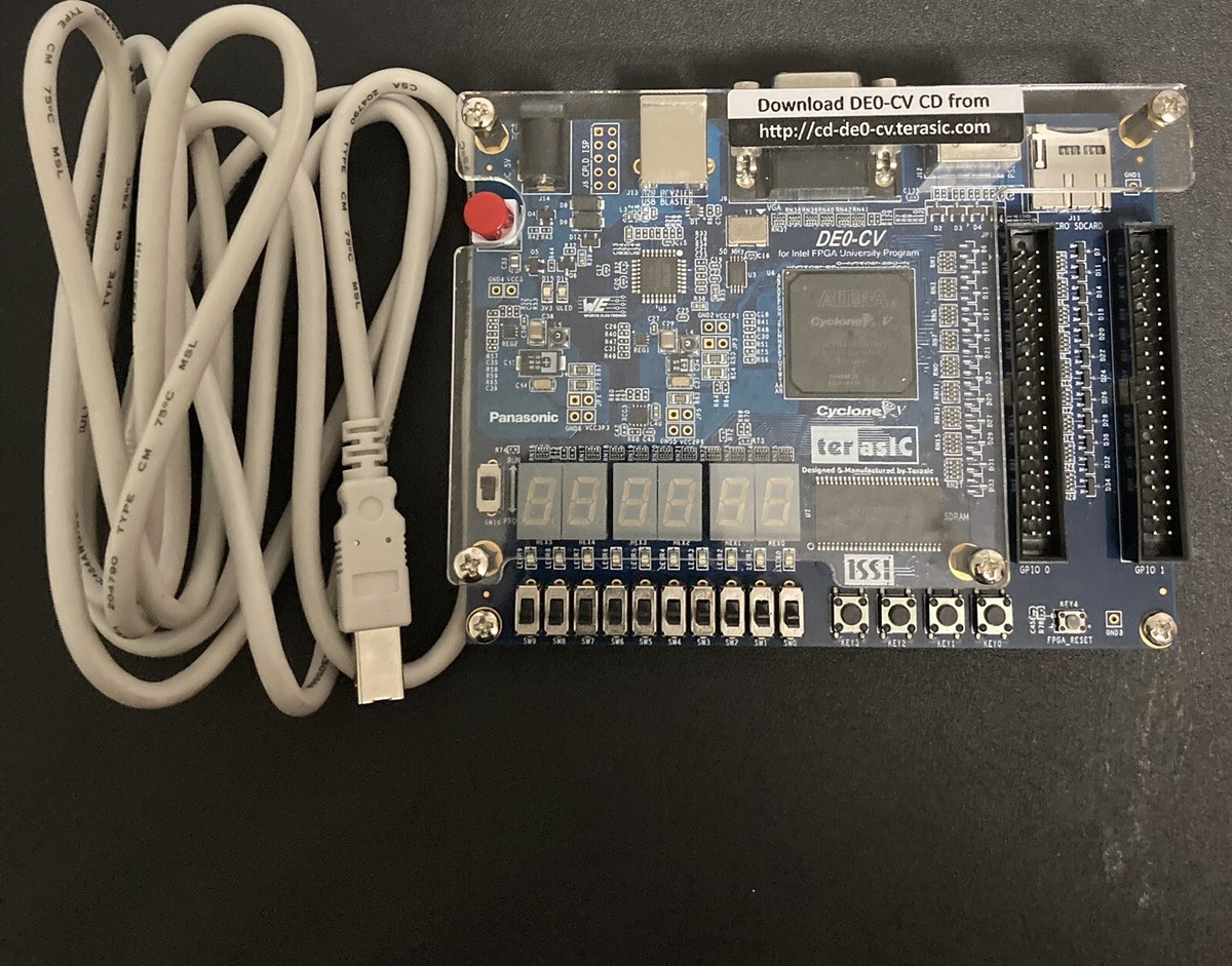
FPGA Vending Machine
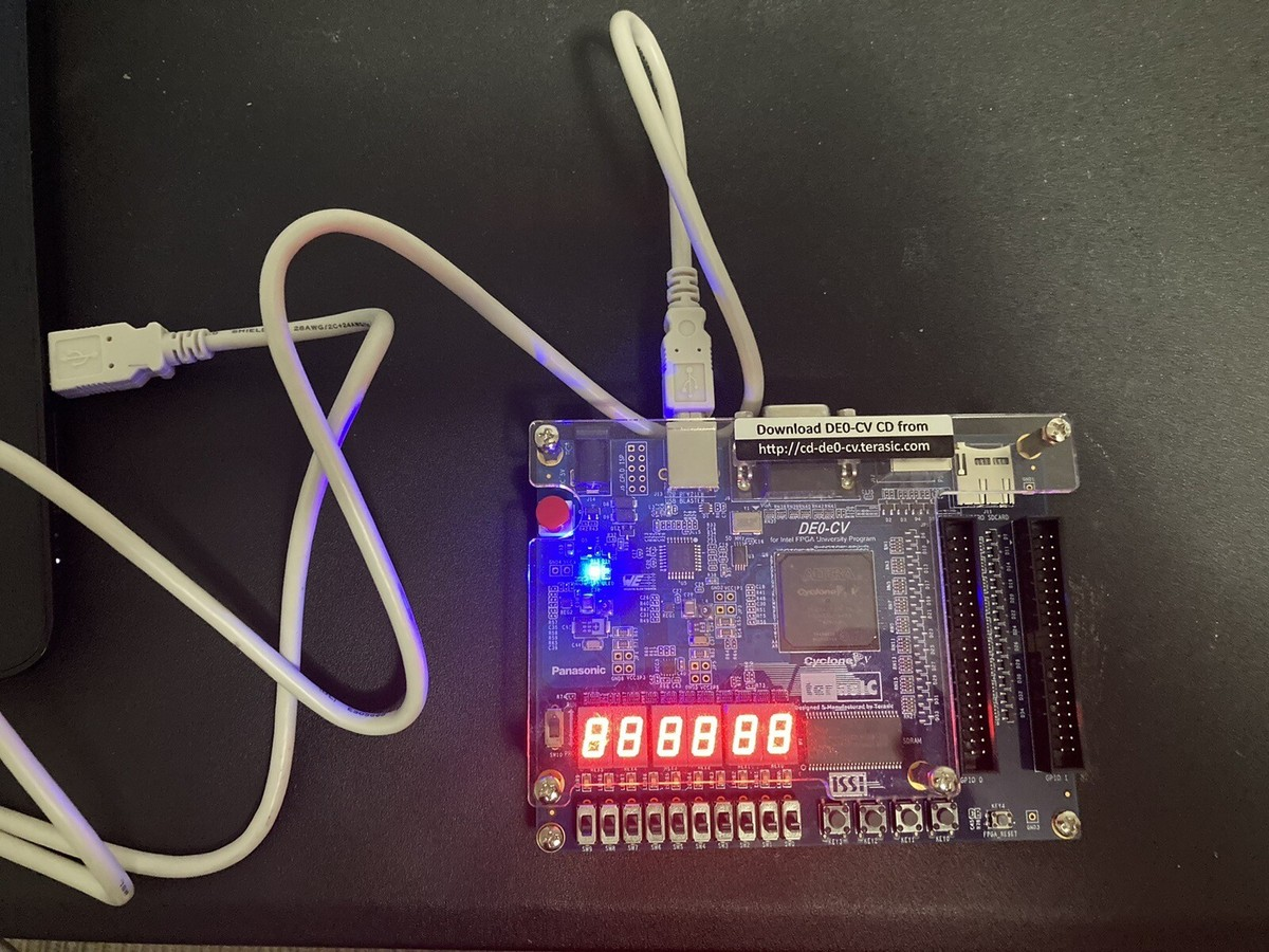
VHDL, Quartus Prime, ModelSim, Altera Cyclone V (DE0-CV FPGA)
I built a finite-state machine (FSM) vending controller in VHDL on a Cyclone V (DE0-CV board) that sells a single product for $0.75. The machine accepts nickels, dimes, and quarters (one at a time), ignores an early Dispense press until credit ≥ $0.75, returns any overpayment immediately, and refunds all money on Coin_Return. Two 7-segment displays (HEX1:HEX0) continuously show the current balance, while Red_Bull and Change_back LEDs indicate dispensing and change return. I mapped inputs/outputs to board switches/LEDs and used a slow clock/manual stepping for human-readable operation during bring-up. Using lookup tables (LUTs) and flip-flops, I modeled the machine’s internal states to ensure correct and reliable transitions.
I structured the controller as a Moore machine with outputs driven by state and a separate clocked “money counter” process (no latches), per best-practice guidance. States and actions (in cents) were:
- wait1: hold balance (idle); watch for coins/refund
- nickel / dime / quarter: add +5 / +10 / +25 then return to wait1 unless we’ve reached the vend threshold.
- enough: balance ≥ 75; safe point to vend; wait for dispense_in. Further coin inputs drop into EXCESS (overpay protection).
- excess: balance > 75; assert Change_back to return extra; while we’re above the price; allow dispense_in or coin_return.
- vend: subtract 75 once, assert Red_Bull; if balance remains, go to CHANGE; otherwise return to wait1
- change: clear balance to 0, assert Change_back, then return to wait1
This table-driven approach made transition logic easy to read and guaranteed that Red_Bull/Change_back depend only on state, not on asynchronous inputs.
- Early Dispense: ignored until credit ≥ $0.75.
- Overpay (e.g., insert after reaching 75): coin is immediately returned (excess → change).
- Coin_Return at any time: refund entire balance and reset to wait1.
- One-coin-at-a-time assumption enforced in the testbench and debouncing logic.
I wrote a binary_to_seven_segment module to convert the current balance (0–99) into tens/ones and drive HEX1/HEX0. This kept the display logic independent from the FSM so the seven-segment always reflected the counter state in real time. On hardware, Dime_In, Nickel_In, Quarter_In, Coin_Return, Dispense were mapped to slider switches / keys, LEDs for Red_Bull and Change_back, and HEX1:HEX0 for the balance.
On the DE0-CV board, I mapped the coin inputs directly to the switches to simulate inserting coins into the vending machine. Each switch represented a different coin value.
- SW0 for nickels
- SW1 for dimes
- SW2 for quarters
This allowed me to flip one switch at a time to add money to the balance. I also assigned SW3 as the coin return input, which refunded all deposited money when toggled, and SW4 as the dispense input to simulate pressing the drink button. Since the onboard 50 MHz clock was too fast for human observation, I configured a pushbutton as a manual clock so I could advance the finite-state machine one step at a time and clearly see each state transition. The reset_n signal was connected to KEY0. The outputs RedBull_out and change_back were mapped to LEDs to show when the drink was dispensed or when change was returned. Finally, the HEX0 and HEX1 seven-segment displays showed the current balance in real time as I toggled the switches, making it easy to visualize how the system reacted to each input.
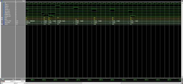
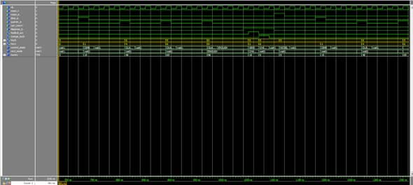
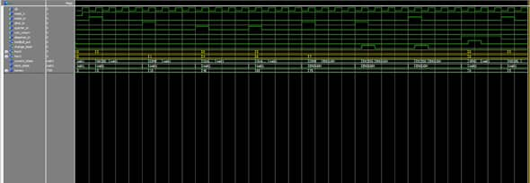
I developed a structured ModelSim testbench with clock/reset generators and stimulus sequences for coin insertion, overpayment, refund, and vend. I verified cycle-accurate waveforms in ModelSim by comparing each signal transition to the expected timing and logic behavior defined in the vending machine specification. For every test sequence, for example: inserting a coin, overpaying, pressing dispense, or activating coin return. I checked that the state transitions, output activations, and balance updates occurred exactly one clock cycle after the corresponding input pulse, with no glitches or race conditions. then synthesized in Quartus, inspected the State Machine Viewer to confirm transitions, and finally downloaded to the DE0-CV to validate real switches/LEDs/HEX I/O.
I built a modular verification setup with two ModelSim testbenches. I had one for the delay/clock unit and one for the vending machine FSM. This is so I could isolate timing from control logic and prove each piece works before integration. In the delay bench, I generated the 50 MHz base clock (PERIOD_c = 20 ns) and used a clean active-low reset; in the second bench I also exposed an enable/step input (S) for slow, deterministic stepping. I gated the clock with a boolean sim_done so the simulation halts cleanly, and I synchronized reset release with WAIT UNTIL clk='1' to guarantee the FSM starts in wait1 on a clock edge rather than mid-cycle.
For the vending machine testbench, I instantiated the UUT and drove edge-accurate stimuli that emulate real user behavior: one-coin-at-a-time pulses on nickel_in, dime_in, and quarter_in; explicit overpayment sequences; refund via coin_return; and dispense via dispense_in. Each stimulus uses precise waits (e.g., 20/60/100 ns) to create single-cycle pulses and give the FSM one clock to transition. I verified three core paths end-to-end in the waveforms: (1) exact change up to 75¢ then dispense_in → RedBull_out asserted and balance decremented; (2) overpay to 90¢ then dispense_in → RedBull_out asserted, balance = 15, followed by change return to 00; (3) refund after partial deposits → immediate zeroing of the balance. Throughout, I checked that change_back only asserts in EXCESS/CHANGE, RedBull_out only in VEND, and that the HEX1:HEX0 displays track the running total exactly (e.g., 00 → 05 → 15 → 40 → 65 → 75 → 90 → 15 → 00). This approach shows I can write deterministic, self-contained testbenches (clock/reset generation, controlled stimuli, graceful shutdown), exercise edge cases, and prove correctness from waveforms before moving to hardware.
Summary: Two targeted testbenches: one for timing, one for control. These testbenches let me verify clock integrity, reset behavior, and every money-handling path (exact pay, overpay with change, refund) with accurate cycles and waveform checks, demonstrating rigorous FPGA verification skills.
*Modelsim waveform simulation
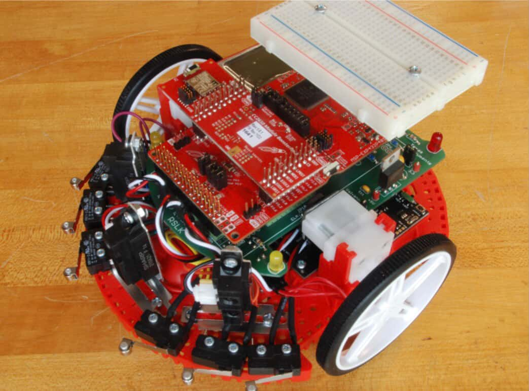
Collision Detection System
TI MSP432 LaunchPad, bump sensors, CCSTUDIO IDE, oscilloscope
For this project, I programmed an embedded collision detection system using the TI MSP432 microcontroller. This program uses bump sensors to detect physical contact and an ultrasonic sensor to calculate distance through time-of-flight measurements. The goal was to make the robot automatically detect obstacles and react in real time to avoid collisions.
The MSP432 LaunchPad controlled the robot’s motors and sensors. The motor driver connections were:
- P5.4 and P5.5 for motor direction (0 = forward, 1 = backward)
- P3.6 and P3.7 to wake up the motor driver
- P2.6 and P2.7 for PWM (Pulse Width Modulation) speed control
PWM is a technique I used to rapidly switch a digital signal on and off to simulate variable voltage, which allows precise control over the motor’s speed. Then, I configured TimerA0 on the MSP432 to generate these PWM signals through Port 2, setting the signal period using TA0CCR0. The duty cycle is how long the signal stays ON during each cycle. It determines how much power is delivered to the motors. The right side motor was controlled by TA0CCR3, and the left side motor by TA0CCR4. The duty cycle was calculated using the formula:
Duty Cycle (%) = (High Time / Period) × 100
In my implementation, I set TA0CCR3 = 2500 and TA0CCR0 = 10000, giving the right motor a 25% duty cycle. This meant the motor received power for 25% of each cycle, allowing it to run at one-quarter of its maximum speed. I chose this setting to keep the robot’s movement controlled and stable during testing, especially when detecting nearby objects or responding to collisions. This precise PWM control helped the system perform smooth turns and obstacle avoidance based on real-time sensor feedback.
I wrote initialization functions like Port2_Init() and Port4_Init() to set up each port for its specific role. The MSP432 doesn’t automatically know how each pin should behave, so I configured them as inputs or outputs using P2DIR and P2SEL. This setup allowed TimerA0 to drive the PWM signals that controlled the motor speed, while other ports handled sensor input and interrupts.
The ultrasonic sensor worked by sending and timing sound pulses to calculate object distance. The MSP432 sent a 10 µs HIGH pulse to the TRIG pin (P6.2), which made the sensor emit an ultrasonic wave. Then it waited for the ECHO pin (P6.3) to go HIGH, signaling that the wave had been sent. I used a hardware timer to measure how long the echo pin stayed HIGH until it went LOW again. This duration represented the round-trip travel time of the sound. Then, I calculated distance using:
Distance = (Speed of Sound × Time) / 2
This logic was implemented in my distanceInCm() and pulseIn() functions. The distance value updated in real time, and I used it with the servo to make the robot change direction when it detected a nearby obstacle, following the next state in my state machine.
For collision detection, I used six bump sensors connected to Port 4 (pins P4.0, P4.2, P4.3, P4.5, P4.6, and P4.7). Each sensor acted as a digital switch that triggered an interrupt on a falling edge when pressed. In my BumpInt.c file, the PORT4_IRQHandler() function handled these interrupts. Using the P4IV register, I identified which sensor was hit and updated a global variable called count.
Each bump sensor was assigned a numerical weight depending on its position:
- Right side sensors (Bump0–Bump2): +3, +2, +1
- Left side sensors (Bump3–Bump5): -1, -2, -3
This simple numerical system allowed the robot to determine where the collision occurred. A positive count meant a hit on the right, a negative count meant a hit on the left, and a near-zero count indicated a direct front collision. This value was then passed to the state machine, which used it to decide how the robot should react, such as reversing or turning away.
To verify that everything worked properly, I used both a multimeter and an oscilloscope. With the multimeter, I confirmed that each bump sensor line was normally high because of the internal pull-up resistors, and that pressing a sensor dropped the voltage, confirming activation. Using the oscilloscope, I visually checked the falling-edge signals to ensure that the interrupts were triggering correctly and that the voltage transitions were clean and reliable.
This testing confirmed that my edge detection and interrupt configurations were working as intended. Overall, this project helped me strengthen my understanding of hardware interrupts, real-time control, and PWM-based motor management.
Power Supply
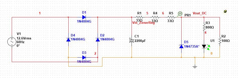
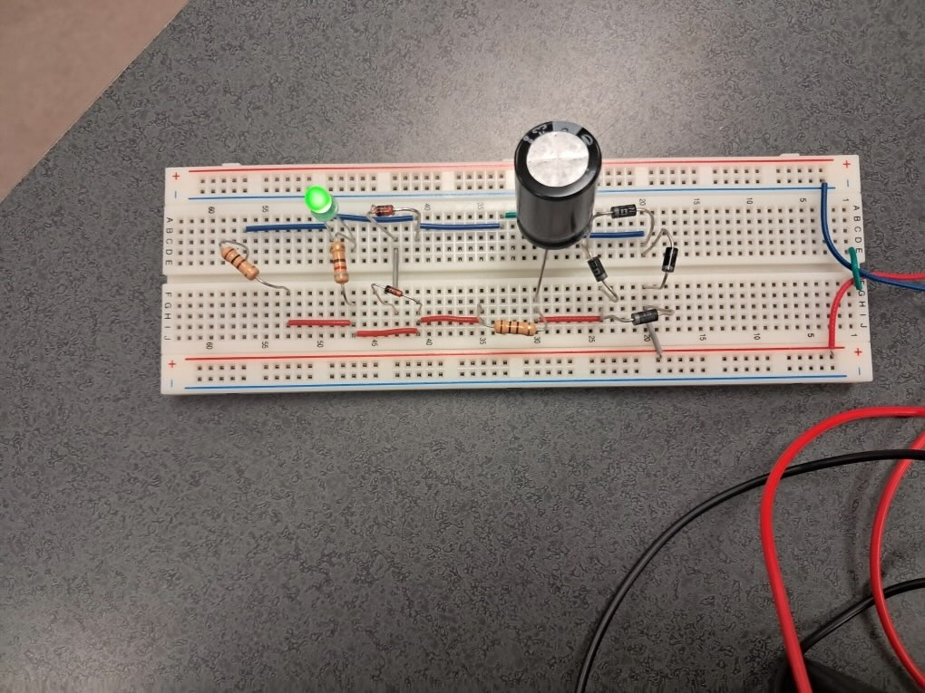
I modeled a 120 V/12.6 V step-down transformer to provide the AC input required for the conversion process. This converts to 12.6 VRMS because 12.6 AC voltage is 12.6 VRMS * √2 = 17.8V. The 120 V would be supplied by a function generator. But on the virtual design(multisim), I just did the math and used an AC 12.6 VRMS voltage and 60Hz because it is the standard power line frequency. 60 hertz (Hz) means the AC current changes direction 60 times per second. In each second, the AC voltage goes through 60 full cycles of positive and negative swings.
I implemented a bridge rectifier using four 1N4004G silicon diodes to convert AC to pulsating DC. Instead of wasting the negative half of the AC cycle (like in a half-wave rectifier), the bridge uses both halves, just flipping the negative one. This is because before you can get a clean, smooth DC voltage, you need to rectify the AC into something that’s one-directional, even if it’s bumpy. The result is a pulsating DC. The voltage is always above zero, but it still rises and falls. In this design, Two diodes are forward-biased (conducting). The other two are reverse-biased (blocking current). Only the conduction diodes drop 0.7V and there are 2 of them. Thus, it has a voltage drop of 1.4V.
A 2200 µF electrolytic capacitor was added to smooth the ripple and provide a more consistent DC signal. The capacitor just needs to match the voltage spec! So to meet the requirement. (math equation solved for capacitor). All filter capacitors in this context serve the same core function: To smooth out the pulsating DC voltage after rectification by storing and releasing charge. After AC goes through the bridge rectifier, you get full-wave rectified DC, which is still bumpy, so the capacitor’s job is to smooth out the pulsating DC that comes from the bridge rectifier. That’s because it’s just the positive halves of the AC signal. It’s not flat yet, just always above zero. The result gives a much smoother DC output (lower ripple), which is important for electronics because electronics expect steady voltage.
I designed a Zener regulator circuit using a 6.8 V Zener diode (1N4735A) and a transistor to stabilize the output voltage across a load range of 0 to 60 mA, ensuring it stayed within the ±10% tolerance window (5.58 V to 6.82 V). I designed this section by thinking of the transistor like a valve and the Zener as the thermostat. The valve opens just enough to let the right voltage through. After the AC is stepped down and rectified: You get a DC voltage that’s higher than needed, which is ~16.4 V after the filtering/capacitor. The Zener diode is reverse-biased and holds a constant voltage (e.g., 6.8 V). The transistor uses the Zener's voltage as a reference: it opens or closes slightly to keep the output voltage stable.The difference between input and output (e.g., 16.4 V – 6.2 V = 10.2 V) is dropped across the transistor. This excess voltage is converted into heat.
A green LED and current-limiting resistor were included at the output stage to signal when the supply is operational. The green LED is an "ON" indicator and it lights up when the power supply output is active and within the expected voltage range (around +6.2 VDC). It acts like a checking factor which only lights up when the correct voltage passes through - forward biased 6.2 V or within 10% of that range.
I used Multisim for circuit design and simulation, and confirmed voltage levels and ripple performance using the virtual tools to generate the graph and numerical values. After confirming, I replicated the circuit on a breadboard with working components and physical oscilloscope probes and function generators.
ABOUT
Brian is a third-year Computer Engineering Technology major at RIT with experience in digital systems, circuit analysis, and microcontroller programming. He is currently a Software Controls Intern at JCS Process & Control Systems for fall 2025.